
P: +86-18866913099
E: sales01@latelas.com
E: sales01@latelas.com
NO 888 Maltsea Industrial Park, Mine Town, Lanling County, Linyi City, Shandong Province, China
Views: 0 Author: Site Editor Publish Time: 2026-11-21 Origin: Site


High-power fiber lasers are only as precise as the assist gas clearing their kerf. Undersizing your air supply leads to dross, burrs, and ruined lenses. Conversely, oversizing inflates energy demands and strains facility infrastructure. Matching a laser air compressor to specific laser power outputs—ranging from 1kW to 30kW and beyond—requires calculating exact volumetric flow rates (CFM or m³/min). You must also determine the sustained pressure (bar) based on nozzle diameters and material thickness. Guesswork here often results in halted production lines and wasted raw materials.
This guide provides the mathematical frameworks, power-to-flow matrices, and equipment evaluation criteria you need. You will learn how to specify the exact compressor configuration for your laser cutting system, ensuring pristine cuts and protected optics.
Flow rate demand scales exponentially with nozzle diameter, not just laser wattage.
Air pressure dictates cutting capability (typically 16-20 bar for standard thick-plate fiber lasers), but sustained volumetric flow dictates cutting quality.
A variable frequency screw compressor minimizes energy waste during idle or low-demand cycles compared to fixed-speed alternatives.
Achieving ISO 8573-1 Class 1.2.1 air purity is non-negotiable to prevent costly focal lens contamination.
To understand compressor sizing, we must first examine the physics inside the laser cutting head. The laser beam simply melts the metal. It does not remove it. The assist gas performs the mechanical work. It acts as a high-velocity broom, blowing the molten slag through the bottom of the cut to create a clean kerf.
Higher power lasers cut faster and penetrate thicker materials. A 12kW laser melts thick carbon steel much faster than a 3kW laser. To flush this larger volume of molten metal quickly, operators must use larger nozzle diameters. A larger nozzle allows a wider column of air to impact the melt pool. However, increasing the nozzle size drastically changes your pneumatic requirements.
Air consumption depends primarily on the orifice size and the operating pressure. We can define this relationship using a conceptual pneumatic flow formula for nozzles:
Q = Cv · A · P
In this framework:
Q represents the volumetric flow rate (m³/min or CFM).
Cv is the specific flow coefficient of the nozzle design.
A represents the cross-sectional area of the nozzle orifice.
P stands for the absolute operating pressure.
Notice the area variable (A). Because the area of a circle is calculated using the square of the radius, small changes in diameter yield massive changes in area. If you upgrade from a 1.5mm nozzle to a 3.0mm nozzle, you double the diameter. This quadruples the orifice area. Consequently, your air flow consumption quadruples. Flow rate scales exponentially with nozzle diameter, independent of the laser wattage itself.
Many fabricators fall into a common sizing trap. They obsess over static pressure. They purchase a compressor simply because it lists a 20-bar maximum rating. Hitting 20 bar of pressure is completely useless if the machine cannot sustain the required m³/min flow rate.
When the laser opens its gas valve, the air expands through the nozzle. If the compressor lacks sufficient volumetric capacity, the pressure will plummet dynamically mid-cut. You might start a cut at 18 bar, but drop to 12 bar within seconds. This pressure drop prevents the gas from clearing the melt pool. The molten metal then welds back together, creating heavy dross and destroying the part.
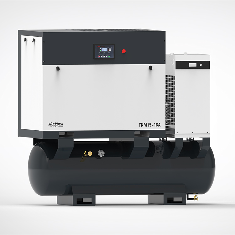
Matching your compressor to your laser requires aligning the machine's capacity with your specific cutting applications. Different power tiers handle different material thicknesses, which dictate different nozzle sizes and gas demands.
Laser Power to Air Compressor Sizing Reference
Laser Power Tier | Typical Material Application | Minimum Sustained Flow Rate | Target Operating Pressure |
|---|---|---|---|
Low to Medium (1kW – 6kW) | Thin sheet metal, HVAC ducting, light brackets | 1.0 – 1.5 m³/min | 16 bar |
High Power (10kW – 20kW) | Thick carbon steel, heavy stainless plates | 2.0 – 3.0 m³/min | 16 – 20 bar |
Ultra-High Power (30kW+) | Heavy industrial manufacturing, ship building | 4.0 – 5.0+ m³/min | 20 – 30 bar |
Shops running 1kW to 6kW lasers typically process thin sheet metal. These applications use smaller nozzles because the melt volume remains low. For these setups, you generally need 1.0 to 1.5 m³/min of flow at 16 bar. This volume provides enough kinetic energy to clear thin kerfs quickly. Oversizing the compressor here wastes floor space and electricity.
High-power machines revolutionize plate processing. They effortlessly slice through thick carbon steel and stainless steel plates. However, they demand aggressive gas assist. Cutting thick plates usually requires 2.0 to 3.0 m³/min of flow at 16 to 20 bar.
Common Mistake: Ignoring piercing demand. Piercing a 20mm thick plate creates an immediate, massive spike in air consumption. If your compressor only meets the continuous cutting demand but ignores the piercing spike, the laser will struggle to break through the material initially. This causes spatter to splash back onto the laser head.
Operating a 30kW+ laser pushes you into heavy industrial manufacturing. These machines cut extreme thicknesses at blistering speeds. They require massive nozzles. You will need 4.0 to 5.0+ m³/min at pressures reaching 20 to 30 bar. In many cases, a single compressor struggles to meet this demand reliably. Facilities often evaluate multiple compressor synchronization. Connecting two or three heavy-duty units in parallel ensures absolute flow stability and provides critical redundancy.
Specifying the right flow rate only solves half the equation. You must also select the correct mechanical technology to generate that air. Industrial environments punish fragile equipment. Your chosen industrial laser air compressor must withstand grueling production schedules.
Historically, smaller shops relied on high-pressure piston compressors. Piston units utilize reciprocating cylinders to compress air. However, they suffer from severe limitations in continuous laser cutting. Piston compressors generate massive amounts of heat and friction. They typically feature low duty cycles (often 60% to 70%). If you run them continuously, they overheat, wear out piston rings, and dump excessive oil into the air stream.
Today, a high pressure screw air compressor serves as the undisputed industry standard. Screw compressors use twin interlocking rotors to compress air continuously. They comfortably handle 100% duty cycles. They run 24/7 without overheating. More importantly, screw compressors deliver constant, smooth air delivery without the damaging pulsations caused by piston strokes.
Energy consumption heavily influences facility operating budgets. Fixed-speed compressors run at maximum RPM whenever they operate. If your laser only demands 50% of the air capacity, a fixed-speed unit vents the excess pressure or idles inefficiently, wasting electricity.
Lasers rarely cut 100% of the time. Operators pause machines for material changes, setup times, and part unloading. Air demand fluctuates constantly. A variable frequency drive alters the compressor's motor speed to match actual air demand perfectly. When the laser stops cutting, the motor slows down. This precise matching prevents immense energy waste, making variable frequency technology optimal for dynamic laser operations.
You must also evaluate your floor plan and scalability. Manufacturers package compressors in two primary formats:
All-in-One Integrated Skids: These 4-in-1 systems mount the compressor, receiver tank, refrigerated dryer, and inline filters onto a single metal pallet. They suit smaller shops perfectly. They minimize installation costs and save valuable floor space.
Standalone Systems: Ultra-high power 20kW+ setups demand standalone modular components. Integrated skids cannot house the massive cooling radiators and oversized dryers required for 4.0+ m³/min flow rates. Standalone units allow facilities to scale individual components. You can upgrade your dryer or add extra receiver tanks independently as your business grows.
Generating the air is only the beginning. You must deliver that air to the cutting head smoothly. Turbulence and pressure drops in the delivery system ruin perfectly good cuts, regardless of how much power your laser generates.
Laser cutting demands laminar, steady gas flow. Micro-fluctuations or pulsations in the air stream cause the molten metal to cool unevenly. This creates visible striations on the cut edge. Worse, pulsation allows molten slag to cling to the bottom of the cut, forming hard dross. Operators must then waste hours manually grinding the edges clean. A stable air supply ensures a smooth, mirror-like finish on stainless steel and clean edges on carbon steel.
You manage flow stability using air receiver tanks. These tanks act as pneumatic batteries. They store compressed air and buffer the system against sudden demand spikes.
Best Practice: Follow the 20-30% rule of thumb. Your receiver tank volume should equal at least 20% to 30% of the compressor’s total CFM output. If your compressor produces 100 CFM, you need at least a 20 to 30-gallon tank capacity. This stored volume stabilizes the 20-bar cutting pressure during rapid piercing cycles. It prevents the compressor from struggling to catch up when the gas valve suddenly snaps open.
The pneumatic pipeline between the compressor room and the laser cutter drastically affects performance. Air experiences friction as it travels through pipes. Long runs, excessive elbows, and undersized pipe diameters cause severe pressure drops. You might generate 20 bar at the compressor, but only deliver 16 bar to the machine.
To minimize pressure drop, place the compressor as close to the laser as facility layout allows. Use smooth-bore aluminum piping instead of traditional black iron pipe. Aluminum resists internal corrosion and minimizes air friction, ensuring maximum pressure reaches the cutting head.
Laser optics represent the most delicate and expensive components of your machine. Feeding dirty, wet air into the cutting head guarantees catastrophic failure. Proper filtration protects your investment.
Compressing ambient air concentrates its natural moisture and airborne particulates. If you use an oil-injected compressor, trace amounts of lubricating oil also enter the air stream. Water aerosols and oil vapor travel through the hoses at high velocities. They ultimately strike the laser's protective windows and focal lenses.
When the intense laser beam passes through these contaminants, it instantly bakes them onto the glass surface. This creates a dark spot. The dark spot absorbs the laser's heat instead of transmitting it. Within seconds, the lens shatters from thermal shock, instantly halting production and requiring expensive replacements.
To prevent lens destruction, your air supply must meet strict ISO 8573-1 Class 1.2.1 standards. You must eliminate moisture, oil, and particulates aggressively.
Moisture Control: You must install a specialized high-pressure refrigerated air dryer. These dryers chill the air, forcing water vapor to condense into liquid for removal. Ensure the dryer achieves a consistent dew point of 2°C to 3°C. For extreme environments or strict manufacturer warranties, you may need a desiccant dryer to achieve even lower dew points.
Oil and Particulate Control: You cannot rely on a single filter. Explain the necessity of 4-stage precision inline filtration. These staged filters progressively remove smaller particles, stepping down to 0.01 micron. Finally, the air must pass through an activated carbon filter. Carbon absorbs gaseous oil vapors that standard particulate filters miss. This is absolutely critical when running oil-injected compressors.
The sequence of your components dictates their effectiveness. Installing filters in the wrong order allows moisture to bypass them. Outline the correct sequence for a high-pressure 20-bar setup. Follow this exact architecture:
Compressor: Generates the high-pressure air.
Wet Tank: Receives hot air, allows initial cooling, and drops out bulk liquid water.
Refrigerated Dryer: Chills the air to remove remaining water vapor.
Precision Filters (4-Stage): Removes solid particulates, aerosols, and oil vapors.
Dry Tank: Stores clean, dry air to buffer dynamic cutting demand.
Laser Cutter: Receives pure, stable assist gas.
Sizing your air supply properly prevents daily production headaches. It remains a precise balancing act between the laser's maximum nozzle output, continuous volumetric flow capacity, and strict air purity standards. You cannot simply buy the largest machine available, nor can you rely on static pressure ratings alone.
Take these actionable steps before purchasing your equipment:
Audit your laser manufacturer’s spec sheet to identify the absolute maximum gas consumption rates for your thickest materials.
Size your compressor's m³/min output to exceed this maximum demand by at least 20% to account for piercing spikes and future nozzle wear.
Consult with a pneumatic engineer to design a smooth-bore pipeline that prevents friction-induced pressure loss between the compressor room and the shop floor.
A: No. Standard shop compressors lack the 16-20 bar pressure required to blow molten metal out of the kerf. Using 8-bar air on thick materials results in failed cuts, severe dross adherence, and excessive heat buildup in the metal, which ultimately ruins the workpiece.
A: Lasers do not cut 100% of the time due to material loading and unloading. A VSD dials down motor RPM and power consumption during these idle periods. This precise load-matching saves up to 30% in energy costs compared to fixed-speed units that idle inefficiently.
A: The pressure will plummet dynamically during the cut. Because the assist gas fails to clear the melt pool, the material will weld back together behind the laser beam. Furthermore, molten slag can splash back upward, severely damaging the laser's protective windows and focal lens.
