
P: +86-18866913099
E: sales01@latelas.com
E: sales01@latelas.com
NO 888 Maltsea Industrial Park, Mine Town, Lanling County, Linyi City, Shandong Province, China
Views: 0 Author: Site Editor Publish Time: 2026-09-28 Origin: Site


Inaccurate sizing of an air system carries heavy financial risks for continuous manufacturing environments. You risk severe pressure drops stalling your automated lines unexpectedly. Conversely, oversizing equipment drives up capital expenditure and wastes thousands annually in inefficient energy consumption. A system built for 24/7 reliability needs a precise, engineering-backed sizing framework. We must approach pneumatic power with the same rigor applied to electrical power.
This guide reveals how to audit your plant demand effectively. We will help you calculate actual pneumatic requirements quickly. You will learn how to move past outdated sizing methods and select the exact technology matching your shift profiles. We provide clear steps to evaluate flow, pressure, and critical environmental factors. By following this framework, you will understand how to procure equipment built for uninterrupted production.
Base your sizing on Required CFM (flow) and PSI (pressure), not Horsepower (HP).
Always calculate a 15–20% buffer for inevitable system leaks and future capacity expansion.
Match your demand profile to the right technology: flat, continuous demand suits fixed-speed units, while variable shift demands require a VFD screw air compressor.
True sizing must account for environmental variables like altitude, ambient temperature, and existing piping infrastructure.
Many plant managers still size machines using horsepower ratings. We must deconstruct this outdated myth immediately. Horsepower only indicates the electrical motor's power consumption. It does not measure actual air generation efficiency. You need precision to size an industrial air compressor correctly for modern automation.
CFM (Cubic Feet per Minute) serves as your primary core sizing metric. In continuous production, CFM evaluates the total simultaneous consumption of all pneumatic equipment. You must know exactly how much air flows through your tools at any given second. Relying on estimates leads to severe production bottlenecks.
PSI (Pounds per Square Inch) acts as your non-negotiable delivery metric. You must carefully define the pressure required by the most demanding piece of equipment on the entire line. Generating higher pressure than necessary creates significant operational waste.
Follow the golden rule of compressed air systems. Every 2 PSI of excess pressure requires 1% more energy from the motor. Emphasize calculating the absolute minimum required PSI. This simple optimization reduces your operational costs dramatically.
Metric | Definition | Impact on Production | Common Mistake |
|---|---|---|---|
Horsepower (HP) | Electrical energy consumed by the motor. | Minimal direct impact. Indicates power, not output. | Assuming higher HP always equals more air volume. |
CFM (Flow) | Volume of air delivered per minute. | Determines how many machines can operate simultaneously. | Failing to account for simultaneous use factors. |
PSI (Pressure) | Force of the air delivered to the tool. | Determines if actuators actuate with enough force. | Over-pressurizing the entire system for one tool. |
Calculating exact demand requires a structured, mathematical approach. We recommend following these three distinct stages.
First, catalog all pneumatic tools, actuators, and air-driven machinery. You need a comprehensive list of everything consuming air on your floor. Imagine a packaging line utilizing pneumatic cylinders, robotic arms, and blow-off nozzles. Each component demands a specific flow rate. A blow-off nozzle might consume 20 CFM continuously. Meanwhile, a pneumatic cylinder might only use 2 CFM intermittently. You must document every single connection point.
Next, determine the duty cycle for each component. This metric indicates the exact percentage of time each tool runs during a shift. In continuous manufacturing, assume a 100% duty cycle for baseline automated equipment. This conservative approach prevents starving your main production lines during peak output hours.
Acknowledge implementation realities early in the sizing process. Even highly maintained plants experience 10–20% air loss through inevitable leaks. Fittings vibrate loose under constant mechanical stress. Rubber hoses degrade rapidly due to synthetic oil exposure and thermal cycling. Air leaks act like invisible holes in your budget.
You must factor a mandatory 15% leak buffer into your initial CFM baseline. This prevents sudden system starvation when multiple lines activate simultaneously. Ultrasonic leak detectors can help identify these hidden losses during routine maintenance, but you must still account for them during initial sizing.
Your facility will inevitably grow. Managers frequently add new production lines without consulting the utility room. Pneumatic tools also degrade over time. An aging air motor consumes significantly more air than a brand new one.
Add an additional 10–15% to your final CFM calculation for future-proofing. This capacity buffer prevents the nightmare scenario of buying a supplementary compressor next year. It gives your maintenance team breathing room.
Follow this calculation workflow:
Sum the CFM of all continuous-use equipment (100% duty cycle).
Calculate the CFM of intermittent tools based on their specific duty cycles.
Add these two numbers to establish your baseline flow.
Multiply the baseline by 1.15 to account for system leaks.
Multiply the new total by 1.15 again to secure your future expansion buffer.
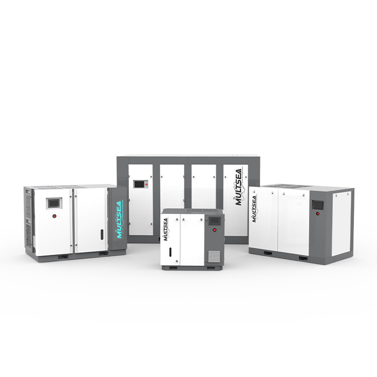
Choosing the right drive technology determines your long-term efficiency.
A stationary screw air compressor excels in very specific industrial environments. It proves ideal for baseline, 24/7 continuous operations where demand rarely fluctuates more than 10%. We consider this the standard workhorse for flat-line manufacturing profiles.
This technology offers lower upfront CapEx and incredibly high reliability. The simple electrical components require minimal specialized maintenance. However, it becomes highly inefficient if plant demand drops. The machine idles, wastes energy, and suffers from blowdown losses. Use it only when you guarantee a flat, continuous demand profile across all shifts.
Many facilities with multiple shifts face wildly fluctuating air demand. A VFD screw air compressor solves this exact problem perfectly. It remains the absolute best choice for varying production lines or fluctuating weekend demand.
The variable frequency drive matches motor speed to exact real-time air demand. If demand drops by 30%, the motor slows down by 30%. While CapEx is higher, the energy savings typically yield a rapid return on investment. Many plants see full payback within 12–24 months simply by eliminating wasteful idling.
Feature | Stationary Screw (Fixed Speed) | VFD Screw Compressor |
|---|---|---|
Ideal Demand Profile | Flat, continuous 24/7 demand. | Fluctuating shifts, variable weekend production. |
Initial Capital Expenditure | Lower upfront cost. | Higher upfront cost (due to inverter drive). |
Energy Efficiency at Partial Load | Poor. Wastes energy idling. | Excellent. Matches motor speed to demand. |
Inrush Current (Start-up) | High spike. Can trigger utility penalties. | Soft start. Gentle on electrical grid. |
Your physical environment directly impacts compressor performance and longevity.
Hot, humid, or high-altitude environments physically reduce air density. Thin air directly lowers the Free Air Delivery (FAD) of the compressor. The machine must work much harder to compress less air.
As a standard rule of thumb, derate compressor capacity by roughly 1% for every 1,000 feet of elevation. You must also adjust for ambient plant temperature. A compressor breathing 100°F air delivers significantly less volume than one breathing 70°F air. Always place air intakes in the coolest possible location.
You must audit your current electrical panel capacity thoroughly. Check both voltage stability and amperage limits before planning an installation. An electric screw air compressor requires specific, robust electrical support.
Consider start-up spikes, known in the industry as inrush current. Fixed-speed models draw massive current spikes when starting up. This can trigger facility demand charges from your utility provider. In contrast, VFD models offer sophisticated soft-start capabilities. They ramp up slowly, protecting your electrical grid from sudden stress.
Poor piping ruins a perfectly sized compressor installation. Undersized diameters, rough interior walls, and sharp elbows cause severe pressure drops. You will have to artificially increase compressor PSI to compensate for bad piping. Never use PVC, as it becomes brittle and poses a severe explosion hazard. Extruded aluminum piping offers the lowest friction coefficient.
Suggest a looped piping system to equalize pressure across the facility. A loop feeds air from multiple directions, minimizing pressure drop at the furthest point. Size your receiver tank correctly to stabilize continuous flow. We typically recommend 1–3 gallons of storage per CFM of compressor capacity. Larger tanks prevent the compressor from short-cycling during brief spikes in demand.
Procurement requires shifting from mathematical sizing to real-world hardware validation.
Evaluating an industrial screw air compressor means looking far beyond marketing brochures. You need cold, hard data. Look for verifiable data on specific energy consumption. Demand that manufacturers provide their kW per 100 CFM rating. This specific metric reveals how efficiently the machine converts electricity into usable compressed air. A lower number indicates a more efficient machine.
Evaluate OEM claims by demanding verified performance data sheets. Standardized documents prevent vendors from manipulating performance numbers. Ensure the equipment can maintain your calculated CFM at your exact required PSI without overheating. Pay close attention to the cooling system specifications.
Your next steps involve strict validation. Advise your team to finalize peak CFM and PSI numbers. Map your electrical constraints clearly, including available breaker space and transformer capacity. Before finalizing a formal Request for Quote (RFQ), request an air demand audit from a trusted vendor. Data logging your current system provides hard evidence. A temporary flow meter and power logger clamped to your existing system will reveal your true usage profile over a full seven-day production cycle.
Sizing an air system correctly secures your manufacturing uptime and profitability. First, audit your equipment comprehensively and identify exact flow needs based on duty cycles. Second, calculate your continuous CFM requirement and add a mandatory 20% safety buffer for leaks and growth. Third, determine absolute PSI minimums to avoid wasting energy on unnecessary over-pressurization.
Finally, select your drive technology based on actual daily demand variance. Take action by installing a flow meter on your main header today. Proper sizing bridges the critical gap between reliable factory automation and sustainable operational costs.
A: No, unless you use a VFD. Oversizing fixed-speed units leads to rapid short-cycling. This causes excessive wear on the airend and massive energy waste. The machine spends too much time idling and blowing down, which destroys internal components prematurely.
A: Screw compressors feature a 100% duty cycle. They are engineered for continuous 24/7 operation without overheating. Piston units generate excessive heat and require frequent cooling breaks, making them unsuitable for automated, non-stop production lines.
A: Inline equipment creates natural pressure drops. Dryers and filters usually consume 3 to 5 PSI. You must size the compressor to generate a slightly higher pressure at the discharge point. This guarantees you deliver the correct PSI at the machine level.
